This topic covers the wiring of the RMC200 D24 Module. See Wiring Guidelines for general wiring information.
The D24 discrete I/O are organized into 4 sections:
|
DI/O # |
Features |
|
|
Group A |
0-7 |
Input or output – nominal 24V. Each I/O points is individually software-configurable as an input or output. Each group is isolated. Within each group, all inputs share the same input common, and all outputs share the same output common. |
|
Group B |
8-15 |
|
|
Group C |
16-19 |
|
|
Fast Inputs |
20-23 |
Inputs only – 5V or 24V. High-speed, supports quadrature encoder inputs and pulse train inputs. Each input is individually isolated. |
Pin-Out
Terminal Block 1 (top)
|
Description |
|
Pin |
|
Description |
|
|
Shield connection |
Case |
1 |
2 |
Case |
Shield connection |
|
Common for group A outputs |
OutCmnA |
3 |
4 |
OutCmnB |
Common for group B outputs |
|
Group A, DI/O point 0 |
D0 |
5 |
6 |
D8 |
Group B, DI/O point 8 |
|
Group A, DI/O point 1 |
D1 |
7 |
8 |
D9 |
Group B, DI/O point 9 |
|
Group A, DI/O point 2 |
D2 |
9 |
10 |
D10 |
Group B, DI/O point 10 |
|
Group A, DI/O point 3 |
D3 |
11 |
12 |
D11 |
Group B, DI/O point 11 |
|
Group A, DI/O point 4 |
D4 |
13 |
14 |
D12 |
Group B, DI/O point 12 |
|
Group A, DI/O point 5 |
D5 |
15 |
16 |
D13 |
Group B, DI/O point 13 |
|
Group A, DI/O point 6 |
D6 |
17 |
18 |
D14 |
Group B, DI/O point 14 |
|
Group A, DI/O point 7 |
D7 |
19 |
20 |
D15 |
Group B, DI/O point 15 |
|
Common for group A inputs |
InCmnA |
21 |
22 |
InCmnB |
Common for group B inputs |
|
Shield connection |
Case |
23 |
24 |
Case |
Shield connection |
Terminal Block 2 (bottom)
|
Description |
|
Pin |
|
Description |
|
|
Shield connection |
Case |
1 |
2 |
Din20+ |
Input 20 + for 12-24 Vdc signals |
|
Shield connection |
Case |
3 |
4 |
Din20+5V |
Input 20 + for 5 Vdc signals |
|
Shield connection |
Case |
5 |
6 |
Din20- |
Input 20 – for all signals |
|
Common for group C outputs |
OutCmnC |
7 |
8 |
Din21+ |
Input 21 |
|
Group C, DI/O point 16 |
D16 |
9 |
10 |
Din21+5V |
|
|
Group C, DI/O point 17 |
D17 |
11 |
12 |
Din21- |
|
|
Group C, DI/O point 18 |
D18 |
13 |
14 |
Din22+ |
Input 22 |
|
Group C, DI/O point 19 |
D19 |
15 |
16 |
Din22+5V |
|
|
Common for group C inputs |
InCmnC |
17 |
18 |
Din22- |
|
|
Shield connection |
Case |
19 |
20 |
Din23+ |
Input 23 |
|
Shield connection |
Case |
21 |
22 |
Din23+5V |
|
|
Shield connection |
Case |
23 |
24 |
Din23- |
|
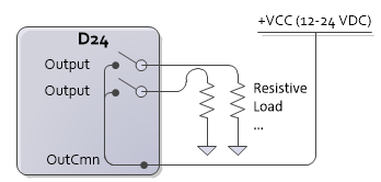
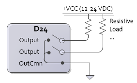
Discrete Outputs
The D24 discrete outputs are solid state relays. The off state is high impedance, the on state is low impedance (8Ω max, 5Ω typical). Max current 75 mA. Max voltage 30 V.
Outputs can be wired in either a high-side or low-side configuration. Because all the outputs in a group share a common, all outputs in the same group must be wired the same.
|
|
|
The load resistance must be sized such that the maximum current through the SSR does not exceed 75 mA. The maximum current is calculated with the following equation:
Current = Vcc / RLoad
For example, if the supply voltage Vcc is 24V, and the load resistance is 480Ω, the current will be:
Current = 24Ω / 480Ω = 50mA
which is under the 75 mA limit.
Using Outputs with Inductive Loads
External fuses should be used to protect the SSRs if there is a possibility of over-current. When switching inductive loads, it is important to place a diode or tranzorb across the load to protect the switch when transitioning from an ”ON” to an ”OFF” state. Otherwise, the collapsing magnetic field can cause a reverse voltage spike in excess of the 30 V rating of the SSR.
SSR switching inductive inductive load with high-side configuration:
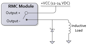
When calculating the current through the SSR, use the same type of calculation as above, with the coil resistance as the load.
Discrete Inputs
To turn on a discrete input, apply a voltage of the correct level. The polarity is unimportant for inputs 0-19, and is important for 20-23.
|
Inputs 0-19 |
Inputs 20-23 |
|
|
Signal Levels |
12-26.4 VDC |
5-26.4 VDC |
|
Max Current Draw |
3 mA |
7 mA |
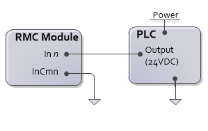
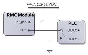
Inputs 0-19
The inputs 0-19 are polarity-independent and can be sinking or sourcing. Inputs 0-19 are divided in three groups: 0-7, 8-15, 16-19. Each group shares a common, so all inputs in a group must be wired the same.
|
Used with a sourcing output
|
Used with a sinking output
|
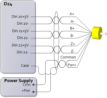
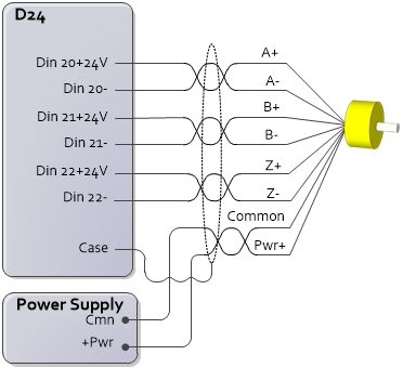
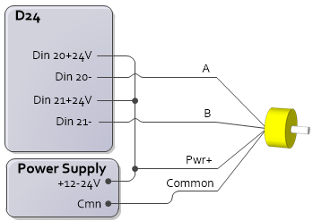
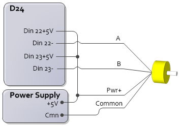
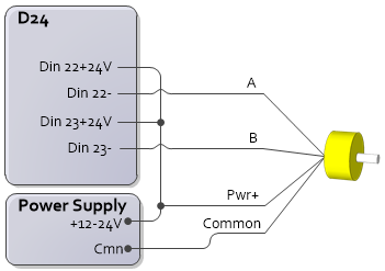
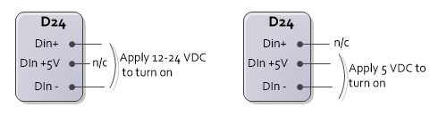
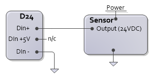
Inputs 20-23
Each input is individually isolated and has Din+, Din +5V, and Din– connections. Use only Din+ or Din+5V, not both.
Example:
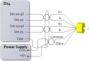
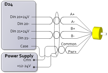
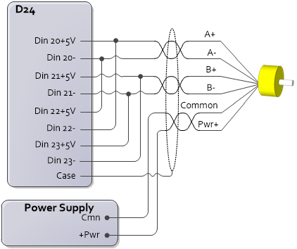
Differential Quadrature Wiring without Wire Break Detection
Use these wiring diagrams for encoders with the outputs listed below. The D24 will not be able to detect a broken wire with this wiring configuration.
5V Differential
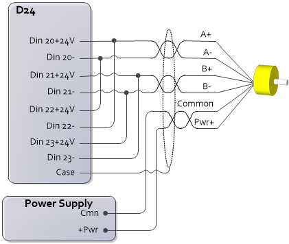
Differential HTL (High Threshold Logic) for signals from 12V to 24 V
RS-422*
*RS-422 will only work in this configuration if the differential output is greater than 3.5V. Some RS-422 drivers may not provide sufficient voltage.
|
With Z (Index)
|
With Z (Index)
|
|
First quadrature input without Z (Index)
|
First quadrature input without Z (Index)
|
|
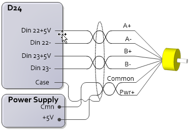
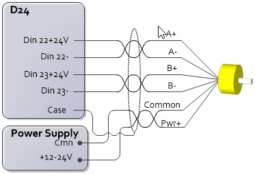
Second quadrature input without Z (Index)
|
Second quadrature input without Z (Index)
|
Differential Quadrature Wiring with Wire Break Detection
Use these wiring diagrams for encoders with the outputs listed below. The D24 will be able to detect a broken wire with this wiring configuration.
5V Differential
Differential HTL (High Threshold Logic) for signals from 12V to 24 V
RS-422*
*RS-422 will only work in this configuration if the differential output is greater than 3.5V. Some RS-422 drivers may not provide sufficient voltage.
|
5V Differential or
|
12-24V Differential or
|
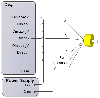
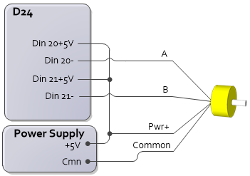
Single-ended Quadrature Wiring
Use these wiring diagrams for encoders with the outputs listed below. The D24 will be able to detect a broken wire with this wiring configuration.
TTL
Push-pull 5V-24V without complements
Open collector from 5V to 24 V
RS-422 (3V)* - Connect A+ and B+ in place of A and B in the diagrams. Encoder wires A- and B- remain unconnected.
*Use RS-422 in this configuration only if the differential output is less than 3.5V. Otherwise, use the differential wiring.
|
Quadrature input with Z (Index)
|
Quadrature input with Z (Index)
|
|
First quadrature input without Z (Index)
|
First quadrature input without Z (Index)
|
|
Second quadrature input without Z (Index)
|
Second quadrature input without Z (Index)
|
See Also
Wiring Guidelines | D24 Module
Copyright © 2026 Delta Computer Systems, Inc. dba Delta Motion