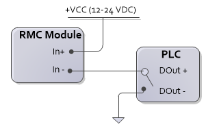
Used with a sourcing output

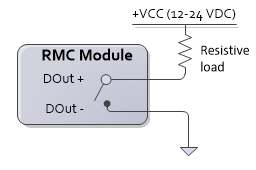
Used with a sinking output
This topic covers the wiring of the RMC200 CPU40 Module. See Wiring Guidelines for general wiring information.
Ethernet
The 2 RJ45 Ethernet ports act as a 3-way switch with the RMC on one port with a single IP address. Accepts an RJ45 Ethernet cable.
USB
Accepts a USB Type B plug. USB connector shielding is grounded with case ground.
Discrete I/O Pin-out
|
Pin |
Label |
Description |
|
1 |
DIn0+ |
General-purpose input 0, 12 -24 Vdc |
|
2 |
DIn0- |
|
|
3 |
DIn1+ |
General-purpose input 1, 12 -24 Vdc |
|
4 |
DIn1- |
|
|
5 |
DOut0+ |
General-purpose output 0, Solid State Relay up to 30 Vdc or peak AC |
|
6 |
DOut0- |
|
|
7 |
DOut1+ |
General-purpose output 1, Solid State Relay up to 30 Vdc or peak AC |
|
8 |
DOut1- |
Discrete Inputs
The CPU40 discrete inputs are compatible with signal levels ranging from 12 to 24VDC. The discrete inputs draw 3mA maximum. Each input is individually isolated.
|
Used with a sourcing output
|
Used with a sinking output
|
Discrete Outputs
The CPU40 discrete outputs are solid state relays. The off state is high impedance, the on state is low impedance (8Ω max, 5Ω typical). Each output is individually isolated. Outputs can be wired in either a high-side or low-side configuration. Outputs can be wired in either a high-side or low-side configuration. Max current 75 mA. Max voltage 30 V.

|
|
See Also
Copyright © 2026 Delta Computer Systems, Inc. dba Delta Motion