This topic covers the wiring of the RMC200 A8 Module. See Wiring Guidelines for general wiring information.
Pin-Out
Terminal Block 1 (top)
|
Description |
|
Pin |
|
Description |
|
|
Input 0 10V Exciter output |
10V Exc |
1 |
2 |
In0+V |
Input 0+ Voltage |
|
Input 0 Common |
Cmn |
3 |
4 |
In0+mA |
Input 0+ Current |
|
Input 0 shield connection |
Case |
5 |
6 |
In0- |
Input 0- |
|
Input 1 |
10V Exc |
7 |
8 |
In1+V |
Input 1 |
|
Cmn |
9 |
10 |
In1+mA |
||
|
Case |
11 |
12 |
In1- |
||
|
Input 2 |
10V Exc |
13 |
14 |
In2+V |
Input 2 |
|
Cmn |
15 |
16 |
In2+mA |
||
|
Case |
17 |
18 |
In2- |
||
|
Input 3 |
10V Exc |
19 |
20 |
In3+V |
Input 3 |
|
Cmn |
21 |
22 |
In3+mA |
||
|
Case |
23 |
24 |
In3- |
||
All the Cmn pins in Terminal Blocks 1 and 2 are internally connected.
Terminal Block 2 (bottom)
|
Description |
|
Pin |
|
Description |
|
|
Input 4 |
10V Exc |
1 |
2 |
In4+V |
Input 4 |
|
Cmn |
3 |
4 |
In4+mA |
||
|
Case |
5 |
6 |
In4- |
||
|
Input 5 |
10V Exc |
7 |
8 |
In5+V |
Input 5 |
|
Cmn |
9 |
10 |
In5+mA |
||
|
Case |
11 |
12 |
In5- |
||
|
Input 6 |
10V Exc |
13 |
14 |
In6+V |
Input 6 |
|
Cmn |
15 |
16 |
In6+mA |
||
|
Case |
17 |
18 |
In6- |
||
|
Input 7 |
10V Exc |
19 |
20 |
In7+V |
Input 7 |
|
Cmn |
21 |
22 |
In7+mA |
||
|
Case |
23 |
24 |
In7- |
||
All the Cmn pins in Terminal Blocks 1 and 2 are internally connected.
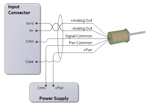
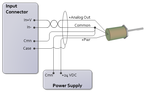
Voltage Transducers
To reduce electrical interference:
In- and Cmn must be connected, either internal to the transducer or externally as close as possible to the transducer.
Use individually shielded twisted-pair wire.
Connect cable shield to earth ground on one end only.
If transducer has only one common, connect Pwr Supply Common and RMC Cmn to it. For best results, make this connection at the transducer.
If the input is disconnected, input voltage will be pulled down ≤ -10V.
4- or 5-wire
3-wire
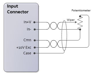
Potentiometer
Use the Exciter pin to increase the measurement accuracy of the potentiometer.
Current Transducers
To reduce electrical interference:
Use individually shielded twisted-pair wire.
Connect cable shield to ground on one end only.
2-wire
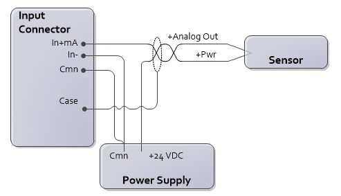
4-wire
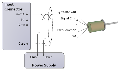
The connection of In- to Cmn should be made as close as possible to the transducer.
See Also
Copyright © 2026 Delta Computer Systems, Inc. dba Delta Motion