To
access this dialog:
Right-click the desired controller in the Project
pane and choose Connection Path.
Or:
On the Controller menu,
click Connection Path.
Use this dialog to enter the Routing Path and Connection Size for the CIP Bridge method of connecting RMCTools to an RMC.
Routing Path
Enter the routing path for connecting RMCTools to an RMC. For details, see Connecting through a CIP Bridge.
The most common scenario is connecting through one ControlLogix PLC, which follows this format:
[IP address 1], 1, [slot number], [Communication Port], [IP address of RMC]
IP address 1:
The IP address of the Ethernet module in the PLC that is connected to the same network as the PC running RMCTools.
1:
Indicates connection from the PLC’s Ethernet module to the backplane.
Slot number:
The slot number in the PLC of the Ethernet module that is connected to the same network as the RMC.
Communication Port:
Specifies which port to use on the PLC’s Ethernet module. Typically this is 2, which indicates Ethernet.
IP address of RMC
The IP address of the RMC. Note that this is a separate network than the network connected to the PC running RMCTools.
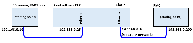
For example, consider this setup:
The CIP routing path is:
192.168.0.25, 1, 7, 2, 192.168.0.200
Where:
1= backplane
7= slot number
2= Ethernet
Connection Size
For more efficient communications, consider choosing 4000 bytes. The default is set to 500 bytes to ensure the communications works on all devices. Most modern Rockwell CIP bridge devices support 4000 bytes.
See Also
Connecting through a CIP Bridge | Connection Path
Copyright © 2026 Delta Computer Systems, Inc. dba Delta Motion