Open topic with navigation
Using Expressions for Commanded Axes
This topic describes the Use
Expressions option in the Commanded
Axes list in user program commands. This allows the commanded axes
to be programmatically selected when the user program is running. This
feature is useful for machines that occasionally may need to disable an
axis but yet run the user programs that normally send commands those axes.
This is an advanced feature that will not
typically be used in most applications.
Overview
The Use Expression
option provides an expression
box to provide a mask for selecting the commanded axes. The expression
must evaluate to a DWORD. The bits in the DWORD correspond to the axis
number. If the bit is set, the command will be sent to the corresponding
axis. If the no bits are set, the command will not be sent to any axis.
Any bits set for which no axis exists will be ignored. For controllers
with more than 32 axes, multiple expression boxes will appear with one
expression box per group of 32 axes.
Example 1: Single Command to Multiple Axes
This example demonstrates how to send a single
command to any axes as set by a variable.
-
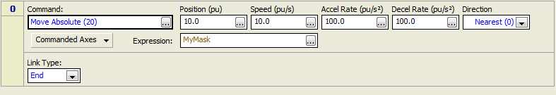
MyMask is as a DWORD variable in the Variable Table.
-
This user program sends a Move Absolute (20) command to the axes defined by the bits set in the MyMask variable:
-
When the user program runs, if bits 0, 1, and 3 are set, then the command will be sent to Axis 0, Axis 1, and Axis 3.
Example 2: One Command to Each Axis
This example demonstrates one method of programmatically
removing one or more axes when sending a set of commands to a set of axes.
-
The following variables are defined:
-
ActiveAxes: A DWORD that will be define which axes should receive commands.
-
Axis1Mask, Axis2Mask, Axis3Mask, Axis4Mask: DWORD variables that will be used as constants. Each of these variables is initialized to a value that has the bit set for its respective axis. The values of these variables must always remain the same.
-
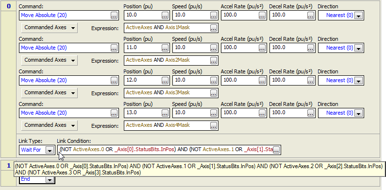
This user program step has one Move Absolute (20) command for each axis. Since the ActiveAxes variable is ANDed with the axis-specific AxisnMask variable, each command can only be sent to the axis specified by the respective AxisnMask variable, and only if the respective bit in the ActiveAxes variable is set.
-
The Wait For Link Condition waits for the In Position bit to turn on for only the selected axes. The expression is too long to be viewed from the Link Condition box, but is shown above in the tooltip window.
Example 3: More than 32 Axes
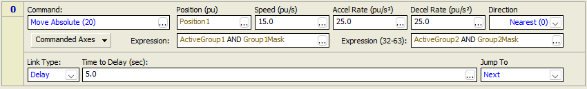
The RMC200 allows for projects with more than
32 axes. When more than 32 axes are used, the Commanded Axes Expression
will have multiple expression boxes. Each box is associated with a respective
32 bit DWORD for the 32 axes specified by each box. All expression boxes
must contain an expression in order for the User Program to verify.
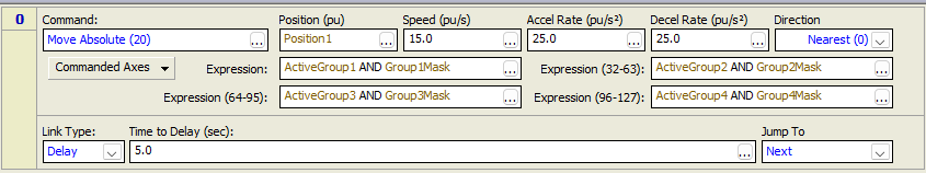
Example 4: More than 64 Axes
See Also
Creating
User Programs | Expressions
Overview
Send comments on this topic.
Copyright © 2026 Delta Computer Systems, Inc. dba Delta Motion