Drive Modes of Operation
The RMC supports EtherCAT drives conforming to the CiA402 drive profile. For general information on using EtherCAT drives with the RMC, see Using Drives with EtherCAT.
The RMC supports the following CiA402 modes of operation:
-
Cyclic Synchronous Position (CSP): The drive calculates the position control loop internally. The RMC continuously sends a target position to the drive.
-
Cyclic Synchronous Velocity (CSV): The RMC continuously receives position data from the drive, calculates the position control loop, and sends a velocity command signal to the drive.
-
Cyclic Synchronous Torque (CST): The RMC continuously receives position data from the drive, calculates the control loop, and sends a torque command signal to the drive.
Setting and Viewing the Mode
The mode of operation is defined by the Mode of Operation object. This object can be viewed in the CoE Object Dictionary. The index, or address, of the Mode of Operation is 0x6060:00. The Mode of Operation is usually set via an INIT command, or is the result of the drive configuration software.
The actual mode of operation is given by the Mode of Operation Display object. This object can be viewed in the CoE Object Dictionary. The index, or address, of the Mode of Operation Display is 0x6061:00.
Some drives include the Mode of Operation and Modes of Operation Display objects in the PDOs. This is unnecessary for the RMC, and they can be removed from the PDO.
The supported mode values are:
|
Mode
|
Value
|
|
CSP
|
8
|
|
CSV
|
9
|
|
CST
|
10
|
A drive may be configured for a specific Mode of Operation via the INIT commands, or via the drive manufacturer’s software.
Local vs. Remote Control
Local and Remote Control specify where the axis’ position PID control is performed:
Local and Remote is selected when defining an axis in the Axis Definitions dialog.
If an RMC200 includes an EtherCAT module, all control axes defined in the controller will be either Local Control or Remote Control. Remote Control is specifically for drives in CSP mode, as described below. All other control axes are Local Control.
Whether an axis is Local Control or Remote Control defines the type of control that is possible, as listed in table below:
|
Control Type
|
Drive Mode
|
PID calculation performed in:
|
Axes Types
|
|
Remote
|
CSP
|
Drive
|
Position only
|
|
Local
|
CSV
|
RMC
|
Position
Position-Pressure
Position-Force
|
|
Local
|
CST
|
RMC
|
Drives and Closed-Loop Control
In addition to connecting to a motor, motor drives usually interface with a position encoder. From the position, drives calculate velocity. Drives also determine the motor torque. Therefore, drives can potentially control torque, velocity, and position. When a drive controls one of these quantities, it is referred to as a ‘control loop’. All servo drives provide a torque control loop. Most also provide a velocity control loop. Some drives, in addition to the torque and velocity loop, provide a position control loop.
The drive Mode of Operation defines which loops are in the drive:
|
|
CSP
|
CSV
|
CST
|
|
Torque Loop
|
✔
|
✔
|
✔
|
|
Velocity Loop
|
✔
|
✔
|
|
|
Position Loop
|
✔
|
|
|
Each loop in the drive must be tuned using the drive manufacturer’s tuning method. Therefore, for CSP mode, all the tuning is performed in the drive. For CSV and CST mode, the drive’s internal loops must first be tuned, then the position loop is tuned in the RMC.
Cyclic Synchronous Position (CSP)
In CSP mode, the RMC continuously sends a target position to the drive and the drive closes the position control loop internally. The RMC does not have any gains or feed forwards. The RMC can monitor the Following Error from the drive and can halt the axis based on the Auto Stop settings.
CSP mode is supported only for position control axes. CSP mode is not supported for dual-loop axes.
Axis Status and Parameter Registers
The following Axis Status and Parameter registers are of particular importance for CSP mode:
-
Target Position Counts
This Axis Status register displays the target position value that is sent to the drive. This is the axis’ Target Position converted by the scaling.
-
Target Position Index
This Axis Parameter specifies the address in the drive to which the Target Position Counts should be sent. The Target Position Index Axis Parameter should typically be set to 0x607A:00.
-
Position Error Index
This Axis Parameter register assigns the following error from the drive to the RMC axis’ Position Error Status Register. This requires that the following error from the drive (0x60F4:00) is included in the PDO data.
If the following error from the drive (0x60F4:00) is not included in the PDO, and the Position Error Index is not properly assigned, the RMC’s Position Error Axis Status Register will not show the true error from the drive. It will instead hold the difference between the Target and Actual Position in the RMC, which will be affected by EtherCAT communication delays.
Setting up CSP Mode
To set up CSP mode:
-
Creating the Axis
When creating an axis in the RMC, in the New Axis Wizard, choose a Control Axis, then choose Remote Control (Main PID in Drive).
-
Configuring PDO Data
Configure the EtherCAT PDO data for the SubDevice so that it includes the items listed below. For details on configuring PDOs, see the Process Data Objects (PDOs) topic. The indexes, such as 0x6041:00, will differ for multi-axis drives.
Input data:
Output data:
The PDO does not need to include the following, so remove them if the PDO is editable:
Velocity Offset:
Some drives, such as the Yaskawa ServoPack SGD7S, may provide improved control in CSP mode if, in addition to the Target Position, the RMC’s Target Velocity is applied to the Velocity Offset object in the drive. This helps the drive perform its internal velocity feed forwards.
To apply the Target Velocity to the drive in CSP mode:
-
Include the Velocity Offset in the PDO:
On the PDO Mapping tab, add the Velocity Offset (0x60B1:00) as an output PDO.
-
Map the Velocity Offset to an RMC Register:
On the Process Data tab, add the Velocity Offset object to the Data Map Address and give it a Tag Name, such as VelocityOffset.
-
Create a User Program:
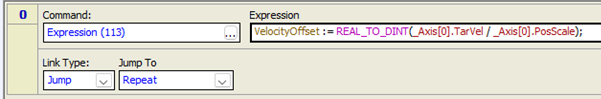
Create a user program that continuously writes the Target Velocity to the drive. The axis’ Target Velocity must be written to the VelocityOffset tag that you created. Since the VelocityOffset is in counts (a DINT), the Target Velocity must first be scaled, typically using the same scale as for the Actual Position, then converted to a DINT. The user program must always run and perform the write each loop time.
Example:
-
Axis Parameters
Configure the following Axis Parameters:
|
Axis Parameter
|
Value
|
|
Position Index
|
0x6064:00
|
|
Control Word Index
|
0x6040:00
|
|
Status Word Index
|
0x6041:00
|
|
Target Position Index
|
0x607A:00
|
|
Position Error Index
|
0x60F4:00
|
-
Mode of Operation
-
Make sure the drive software has been configured to start in CSP mode,
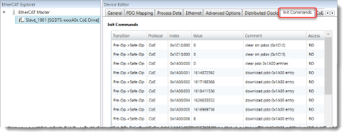
otherwise, make sure the Init Commands are set for CSP mode:
-
In the EtherCAT Editor, select the SubDevice, then select the Init Commands tab.
-
In the Init Commands list, scroll down to Index 6060 and click that row. If this row doesn’t exist, click the New button and add Object 6060 to the Init Commands.
-
In the Edit Value section below the Init Commands list, set the Value to 8, which indicates CSP mode.
-
The PDO need not include the following, so remove them if the PDO is editable:
In addition to the steps above, the position feedback will need to be scaled.
Cyclic Synchronous Velocity (CSV)
In CSV mode, the RMC continuously receives position data from the drive, closes the control loop, and sends a velocity command signal to the drive. This is referred to as Local control (Main PID in RMC) with velocity output.
The RMC supports CSV on position control axes and does support dual-loop control, such as position-force control.
Axis Status and Parameter Registers
The following Axis Status and Parameter registers are of particular importance for CSV mode:
-
Drive PID Output Mode
This Axis Parameter defines whether the output is a velocity or torque. For CSV, it should be set to Velocity Output.
-
Final Output
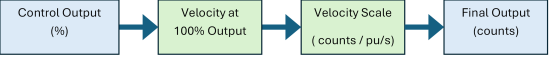
This Axis Status register displays the velocity command value that is sent to the drive. This is the Control Output converted by the Velocity at 100% Output and Velocity Scale.
-
Target Velocity Index
This Axis Parameter specifies the address in the drive to which the Final Output should be sent. The Target Velocity Index Axis Parameter should typically be set to 0x60FF:00.
-
Velocity at 100% Output
This Axis Parameter converts the axis’ Control Output into a commanded output velocity to be sent to the drive. To set this value, consider how fast you want the drive to move the system when the RMC gives the maximum 100% Control Output.
-
Velocity Scale
This Axis Parameter defines the conversion between the commanded output velocity to the Final Output.
The Velocity at 100% Output and Velocity Scale work together as follows:
Setting up CSV Mode
To set up CSV mode:
-
Creating the Axis
When creating an axis in the RMC, in the New Axis Wizard, choose a Control Axis, then choose Local Control (Main PID in RMC).
-
Configuring PDO Data
Configure the EtherCAT PDO data for the SubDevice so that it includes the items listed below. For details on configuring PDOs, see the Process Data Objects (PDOs) topic:
Input data:
Output data:
Note that the indexes will differ for multi-axis drives.
The PDO need not include the following, so remove them if the PDO is editable:
-
Axis Parameters - Scaling
Configure the following axis feedback parameters:
-
Position Scale
-
Position Offset
If is it not possible to set the Position Offset yet, that can be done later. It is important to set the Position Scale.
-
Axis Parameters - Output
Configure the following output Axis Parameters:
-
Position Index: 0x6064:00
-
Control Word Index: 0x6040:00
-
Status Word Index: 0x6041:00
-
Drive PID Output Mode: Set to Velocity Output
-
Target Velocity Index: 0x60FF:00
-
Velocity at 100% Output:
Set to the maximum velocity of the axis when the Control Output is 100%.
-
Velocity Scale:
Set to scale the commanded output velocity to counts in the drive. Typically, for CSV mode, this is the same as the Position Scale.
-
Mode of Operation
-
Make sure the drive software has been configured to start in CSV mode, otherwise, make sure the Init Commands are set for CSV mode:
-
In the EtherCAT Editor, select the SubDevice, then select the Init Commands tab.
-
In the Init Commands list, scroll down to Index 6060 and click that row. If this row doesn’t exist, click the New button and add Object 6060 to the Init Commands.
-
In the Edit Value section below the Init Commands list, set the Value to 9, which indicates CSV mode.
-
The PDO need not include the following, so remove them if the PDO is editable:
Cyclic Synchronous Torque (CST)
In CST mode, the RMC continuously receives position data from the drive, closes the control loop, and sends a torque command signal to the drive. This is referred to as Local control (Main PID in RMC) with torque output.
The RMC supports CST on position control axes and does support dual-loop control, such as position-force control.
Axis Status and Parameter Registers
The following Axis Status and Parameter registers are of particular importance for CSV mode:
-
Drive PID Output Mode
This Axis Parameter defines whether the output is a velocity or torque. For CST, it should be set to Torque Output.
-
Final Output
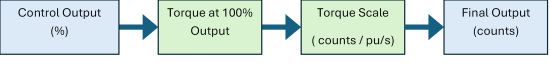
This Axis Status register displays the Torque command value that is sent to the drive. This is the Control Output converted by the Torque at 100% Output and Torque Scale.
-
Target Torque Index
This Axis Parameter specifies the address in the drive to which the Final Output should be sent. The Target Torque Index Axis Parameter should typically be set to 0x6071:00.
-
Torque at 100% Output
This Axis Parameter converts the axis’ Control Output into a commanded output velocity to be sent to the drive. To set this value, consider how much torque you want the drive to apply to the system when the RMC gives the maximum 100% Control Output.
-
Torque Scale
This Axis Parameter defines the conversion between the commanded output torque to the Final Output.
The Torque at 100% Output and Torque Scale work together as follows:
Setting up CST Mode
To set up CST mode:
-
Creating the Axis
When creating an axis in the RMC, in the New Axis Wizard, choose a Control Axis, then choose Local Control (Main PID in RMC).
-
Configuring PDO Data
Configure the EtherCAT PDO data for the SubDevice so that it includes the items listed below. For details on configuring PDOs, see the Process Data Objects (PDOs) topic:
Input data:
Output data:
Note that the indexes will differ for multi-axis drives.
The PDO need not include the following, so remove them if the PDO is editable:
-
Axis Parameters - Scaling
Configure the following axis feedback parameters:
-
Position Scale
-
Position Offset
If is it not possible to set the Position Offset yet, that can be done later.
-
Axis Parameters - Output
Configure the following output Axis Parameters:
-
Position Index: 0x6064:00
-
Control Word Index: 0x6040:00
-
Status Word Index: 0x6041:00
-
Drive PID Output Mode: Set to Torque Output
-
Target Torque Index: 0x6071:00
-
Torque at 100% Output:
Set to the maximum torque of the axis when the Control Output is 100%.
-
Torque Scale:
Set to scale the commanded output torque to counts in the drive.
-
Mode of Operation
-
Make sure the drive software has been configured to start in CST mode, otherwise, make sure the Init Commands are set for CST mode:
-
In the EtherCAT Editor, select the SubDevice, then select the Init Commands tab.
-
In the Init Commands list, scroll down to Index 6060 and click that row. If this row doesn’t exist, click the New button and add Object 6060 to the Init Commands.
-
In the Edit Value section below the Init Commands list, set the Value to 10, which indicates CST mode.
-
The PDO need not include the following, so remove them if the PDO is editable:
See Also
EtherCAT Overview
Send comments on this topic.
Copyright © 2025 Delta Computer Systems, Inc. dba Delta Motion