Note: This Mitsubishi protocol was added to the RMC SERIAL module in 20051214 firmware. Modules with firmware dating prior to this do not support this protocol.
Introduction
Use the Bidirectional protocol to communicate with the RMC100 from a Mitsubishi Q series PLC with a QJ71C24 serial communication module. For details on communicating with an FX series PLC, see the sing the Using the Mitsubishi No Protocol with the RMC SERIAL topic.
Configuring
Both the RMC and the Mitsubishi are very flexible and provide many options for configuring the serial ports.
RMC SERIAL Settings:
Use the Serial Module Options dialog box as described in Configuring the RMC SERIAL to select the following options for the RMC SERIAL:
Baud Rate
Data Bits
Parity
Mitsubishi PLC Settings:
Set the QJ71C24 intelligent function module switches for the desired serial settings. The serial settings on the Mitsubishi must match the settings on the RMC100. For details on the Mitsubishi serial settings, see section 4.5.2 of the Mitsubishi manual: Q Corresponding Serial Communication Module (User’s Manual).
The sample GX Developer program RMCBIDIR should be used as a starting point for any Mitsubishi Q program using a RMC Serial module.
Sample Program
Delta has provided a sample GX Developer program (created with version 8.25B) called RMCBIDIR, available on the Downloads page of Delta's website at www.deltamotion.com. This program should be used as a starting point for any Mitsubishi Q program using a RMC Serial module.
Protocol Description
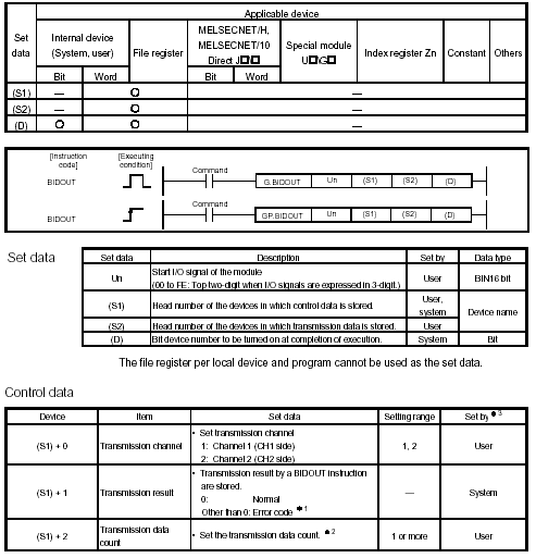
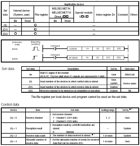
This protocol requires that the PLC program uses the BIDOUT and BIDIN instructions. A detailed explanation is found in the following Mitsubishi manual: Q Corresponding Serial Communication Module (User’s Manual).
BIDOUT Instruction:

BIDIN Instruction:

Reading from the RMC100
To read data, first use the BIDOUT instruction to request the data, then use the BIDIN instruction to read the data.
The Head number of the data sent to the RMC100 is designated by (S2) in the BIDOUT instruction. The data must be according to the following format:
Each box is a 16-bit word.

Count: The number of registers to read.
Address: The address of the first register to read. The address follows the PROFIBUS address format. See the PROFIBUS Register Map topic in the RMCWin help for details.
After receiving the request, the RMC100 will return the requested data. The BIDIN instruction is used to read the data. The X3 bit in the QJ71C24 will turn on when there is data available to be read from the QJ71C24 buffer. To read the returned data, (D1) in the BIDIN instruction indicates the head number of the device to store the data in.
Writing to the RMC100
The head number of the data sent to the RMC100 is designated by (S2) in the BIDOUT instruction. The data must be according to the following format:
Each box is a 16-bit word.

Count: The number of registers to write to. The count must be negated to indicate that it is a write. For example, to write to 6 registers, the count must be -6.
Address: The address of the first register to write to. The address follows the PROFIBUS address format. See the PROFIBUS Register Map topic in the RMCWin help for details.
Value x: The data values to be written to the RMC100.
Copyright (c) 1997-2015 by Delta Computer Systems, Inc.