DirectLogic PLCs from Automationdirect.com (formerly PLC Direct) can be used to control the RMC over Ethernet. Currently two families of DirectLogic PLCs have Ethernet modules available to them: the DL205 and the DL405. The DL205 requires the H2-ECOM Ethernet module, while the DL405 requires the H4-ECOM. Both Ethernet modules are also sold through Automationdirect.com.
Note: Ethernet communication with the DirectLogic PLCs and ECOM modules requires RMC ENET firmware dated 20000913 or later.
As of this writing, the DL205 family includes the D2-230, D2-240, and D2-250 CPUs. The DL405 family includes the D4-430, D4-440, and D4-450 CPUs. The following chart lists the limitations of the various CPUs when used with the RMC and Ethernet.
|
Family |
CPU |
Limitations |
|
DL205 |
D2-230 |
No Ethernet support. Cannot be used with the RMC ENET. |
|
|
D2-240 |
Severely limited support. Review Register Map before using. |
|
|
D2-250 |
Cannot use Plots. |
|
DL405 |
D4-430 |
Cannot use Plots and the Spline Download Area. |
|
|
D4-440 |
Cannot use Plots. |
|
|
D4-450 |
Cannot use Plots. |
Note: The documentation below assumes the user to be familiar with DirectLogic PLC programming, and instead focuses on how to initiate reads and writes to an RMC.
The standard method of initiating data transfers from a DirectLogic 205/405 PLC is to use the RX and WX instructions. These instructions send data over raw Ethernet packets without using TCP/IP at all. This results in better performance, but limits the PLC-to-PLC communication to a single network (packets can not be routed to other networks or the Internet). Because IP is not used, IP addresses cannot be used. In their place, each device has a unique Module ID ranging from 1 to 90.
Setting the RMC Module ID
Automationdirect.com ships a setup program called NetEdit with the ECOM manual. It can also be downloaded from their supplier's site: http://www.hosteng.com. This program can be used to set the Module ID of any ECOM or RMC module.
To set the RMC Module ID:
Ensure that your PC has TCP/IP installed.
Connect your PC and the RMC to the same network. Generally this involves plugging each into the same Ethernet switch or hub.
Start NetEdit on your PC.
Under Protocol, select UDP/IP. The program will take approximately 1 second to scan the network for devices.
You should now see one or more devices in the Module list. The devices beginning with 00 50 A0 are RMCs. Devices beginning with 00 E0 62 are most likely ECOM modules.
Click the RMC in the Module list. The rest of the NetEdit application should update to hold the information for the RMC. The Name will default to Delta RMC, even though the Type under Module Information will be H2-ECOM for compatibility.
In the Module ID text box under Configuration, enter the Module ID you wish to use. This ID must be unique for all devices on your network. This value must be between 1 and 90 to be usable by other PLCs.
If you wish, you can also set your IP Address and IP Netmask (Subnet Mask) fields at this time. They are not required to be set up to use the RMC with the ECOM modules.
Note: The Name and Description fields in the RMC can be changed, but because they serve no purpose for the RMC, they will return to their default values when power is cycled.
Click Update. This will save the Module ID, IP Address, and Subnet Mask in the RMC Flash memory. Do not power down the RMC until the RMC's CPU LED stops blinking (this takes approximately seven seconds).
For further details on using NetEdit, see its documentation in the ECOM manual from Automationdirect.com.
Reading and Writing RMC Data from the DL205/405
The ECOM manual describes reading and writing data from other PLCs in Chapter 3: RLL Programming for Communications of its original version (4/98). Use the exact same procedure for reading and writing from the RMC; the RMC emulates an H2-ECOM. Refer to the RMC Register Map (Automationdirect.com) topic for a list of addresses in the RMC that can be read or written.
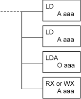
The following is the format of the RX and WX routines:

The first three instructions load three values onto the accumulator stack, and the RX or WX instruction takes these values off the accumulator stack and uses them for preparing the data to send over the network. Therefore, you have some flexibility as to how to put the values on the accumulator stack—for example, in the LD instructions you can use K to specify constants or V to specify a register holding the value to put on the stack. For the most part these additional methods are not described in this manual but can be found in the DL205 PLC User Manual and DL405 PLC User Manual.
Note: Recall that DirectLogic V-memory addresses are given in octal. Refer to the DL205/405 PLC User Manual for a description of octal.
Here is a description of the values placed on the stack:
|
Value |
Description |
|
First (LD) |
This 16-bit BCD value is divided into three fields. The first digit indicates the base number. In most cases this must be 0 to indicate the CPU base. The second digit indicates the ECOM slot number. Slots start with 0 for the first slot to the right of the CPU and increase by one for each slot to the right. The last two digits indicate the Module ID of the remote device. Enter the RMC's Module ID here. |
|
Second (LD) |
This 16-bit BCD value indicates the number of bytes to read or write. For RMC registers, this value must be an even number between 2 and 128, which represent 1 to 64 words. |
|
Third (LDA) |
This indicates the location in the local PLC to read the data into, and write data out from. The address is a V-memory address, even though the prefix is O (for octal) instead of V for V-memory. |
|
Fourth (RX or WX) |
The parameter on the RX or WX instruction indicates the location in the remote PLC (the RMC in our case). See RMC Register Map (Automationdirect.com) for a map of addresses. Notice that V0-V177 and V1000-V1177 may be displayed as TA0-TA177 and CTA0-CTA177, which are called aliases. You can disable displaying aliases by selecting the View menu in DirectSOFT32, Options menu item, Global tab, and clearing the Display Aliases checkbox. |
Example 1
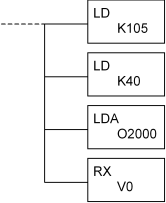
The user has an ECOM in slot 1 of the CPU base and an RMC with Module ID 5. The user wants to read all ten status words for each of the first two axes of the RMC and store those twenty words into V2000-V2023. This is done as follows:

Example 2
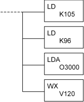
The user has an ECOM in slot 1 of the CPU base and an RMC with Module ID 5. The user wants to write all six command words to all eight axes on the RMC, using the commands in V3000-V3057. This is done as follows:

Indirect Addressing
When communicating with the RMC with its large memory map, there may be times where it is desirable to read continuous blocks of data. For example, since only 64 words can be read at a time, to read the entire 2048-word Event Step table would require 32 reads. The first read would start at V2000, the second would start at V2100, and so on. You can take advantage of V-memory pointers (P type) for the RX and WX parameter. Again, this is out of the scope of RMC documentation and the user should refer to the DL205/405 PLC User Manual for details.
Copyright (c) 1997-2015 by Delta Computer Systems, Inc.