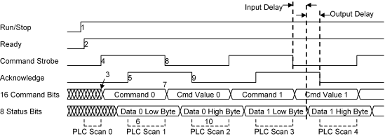
This mode allows any motion controller command to be sent to the motion controller using the Communication Digital I/O. In addition, it allows the user to request a wide range of status information back, including ACTUAL POSITION. This mode is more complicated than the other modes and requires a PLC to communicate with the RMC, but it is much more capable than the other Communication Digital I/O modes.
Refer to Features Shared by All Modes for details for input and output assignments that are common to all modes.
Basic Operation
In this mode, commands and status information are sent between the motion controller and the programmable controller using the following sequence of steps:

Raise the CPU input 0. This input is also called Run/Stop. CPU input 1 should start low.
Wait for the CPU output 0 to raise. This input is called Ready.
Place a 16-bit command word on digital inputs 0-15. This word gives the command type and also information for which data is requested back. See Command Words for Command Mode for details on using this word.
Raise the Command Strobe.
Wait for CPU output 1 to toggle. This output will be called Acknowledge from here forward.
Read digital outputs 0-7, which will hold bits 0-7 of the data just requested.
If the command sent in the previous steps requires a command value (such as a requested position), place the 16-bit command value on digital inputs 0-15.
Lower the Command Strobe.
Wait for Acknowledge to toggle. At this point the command will be have been executed.
Read digital outputs 0-7, which will hold bits 8-15 of the requested data. Although the requested data may be changing constantly, the entire 16 bits is latched when the command is first executed. It is this latched data that is outputted byte by byte.
These steps should be processed by the PLC so that a complete new command can be sent every two PLC scans. To achieve this, the following steps should be taken:
1st scan:
Perform step 1.
2nd scan:
Perform steps 2 through 4 to send first half of first command.
3rd scan:
Perform steps 5 through 8 to send the second half of first command.
4th scan:
Perform steps 9 and 10 to finish receiving the data requested by the first command.
Perform steps 3 and 4 to send first half of second command.
5th scan:
Perform steps 5 through 8 to send the second half of second command.
6th scan:
Perform steps 9 and 10 to finish receiving the data requested by the second command.
Perform steps 3 and 4 to send first half of third command.
… (Repeat the last two scans for each new command)
Configuring Command Mode
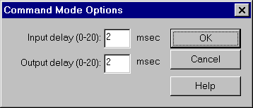
This is done using the Command Mode Options dialog box:

To use this dialog box:
On the Tools menu, click Module Configuration.
In the Slots list, click the Comm Digital I/O item.
Click Slot options.
In the DI/O mode list, click Command.
Click Mode options.
Select the desired options.
Click OK.
Click Update RMC.
The Update Module Configuration dialog box will be displayed to indicate the progress. If the module could not be reset automatically, you may be prompted to reset the module manually.
Input Delay
Digital inputs 0-15 are not stored in the RMC module until the Command Strobe input (CPU in 1) transitions from low to high or from high to low. However, it is possible that the inputs are not stable for some time after that. Therefore, the Input Delay value can be set to make the motion controller wait a number of milliseconds after the Command Strobe input toggles before reading inputs 0-15. This is especially important if relays are used to drive these inputs.
Output Delay
Digital outputs 0-7 are set by the motion controller before the Acknowledge output (CPU out 1) is toggled. However, it takes a small amount of time for these outputs to settle, and additionally, the inputs reading these lines may take more time to register the outputs. Therefore, the Output Delay value can be set to make the motion controller wait a number of milliseconds after setting the digital outputs before toggling the Acknowledge output.
Copyright (c) 1997-2015 by Delta Computer Systems, Inc.